logo elektroda
logo elektroda
X
logo elektroda
REKLAMA
REKLAMA
Adblock/uBlockOrigin/AdGuard mogą powodować znikanie niektórych postów z powodu nowej reguły.

APC Back-UPS Pro 550 BR550GI - Brak ładowania akumulatora

sunlux 15 Gru 2018 00:00 8727 6
REKLAMA
  • #1 17627774
    sunlux
    Poziom 20  
    Posty: 653
    Pomógł: 20
    Ocena: 120
    Witam.

    APC Back-UPS Pro 550 BR550GI - Brak ładowania akumulatora
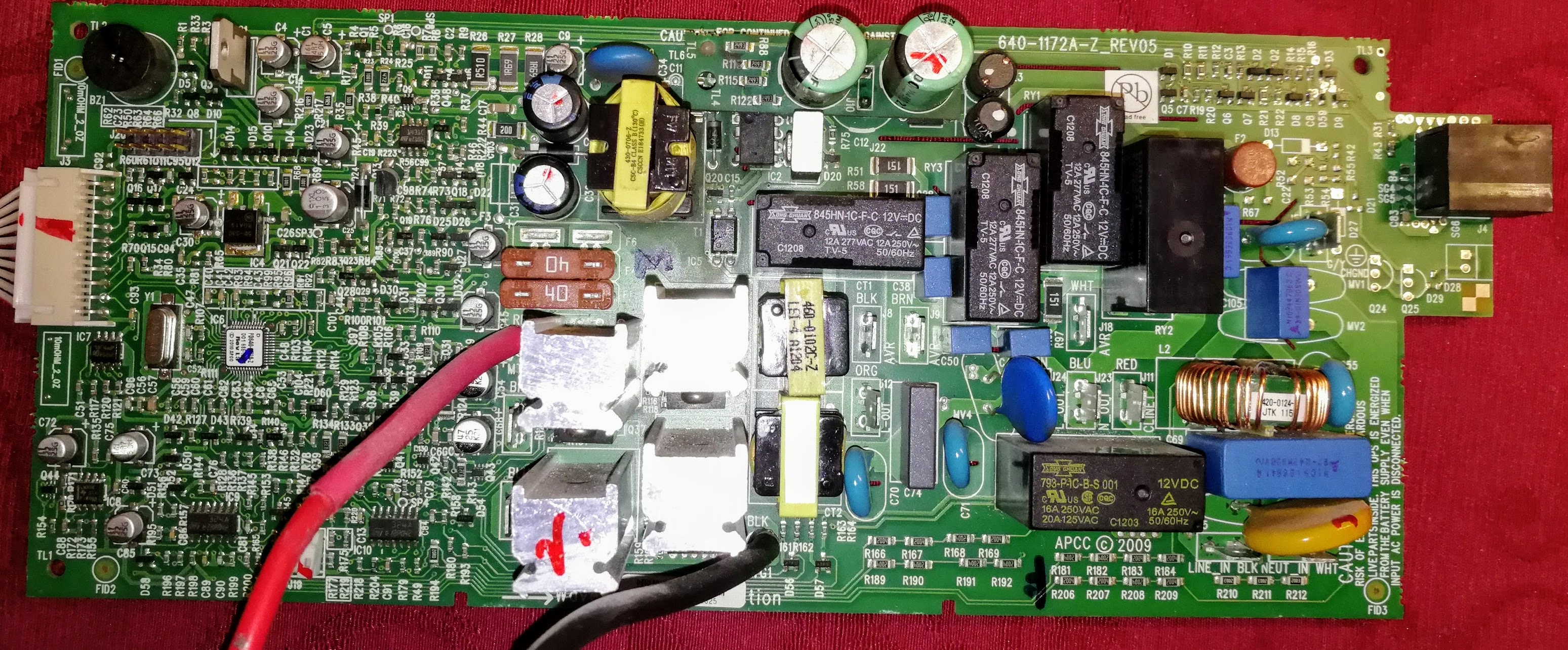
    Płyta główna zasilacza APC Back-UPS Pro 550 BR550GI to 640-1172A-Z_REV05.

    Po zainstalowaniu naładowanego akumulatora zasilacz działa prawidłowo w tym sensie, że przy braku zasilania z sieci działa przetwornica zasilając podłączony odbiornik do momentu rozładowania akumulatora. Akumulator nowy i sprawy EuroPower 12V/7Ah. Po rozładowaniu akumulatora zasilacz już nie włącza się ponieważ nie działa układ ładowania akumulatora. Akumulator nie jest ładowany więc zasilacz działa tylko do momentu rozładowania akumulatora, później nie można go już włączyć. Czy spotkał się już ktoś z tym w przypadku tego konkretnego modelu i płyty głównej? Jakieś wskazówki gdzie szukać usterki?

    W Back-UPS RS 500 to była typowa usterka i przegrzewanie się zawsze tej samej części płytki drukowanej co prowadziło go uszkodzenia układu ładowania akumulatora. Czasami pomagała tam wymiana kondensatora C7 22µF/16V, ale tutaj w BR550GI nie widać typowo miejsca przegrzania.
  • REKLAMA
  • Pomocny post
    #2 17631812
    lisek
    Serwisant RTV
    Posty: 39780
    Pomógł: 6320
    Ocena: 6823
    Za ładowanie odpowiada TNY278PN + tranzystor
    Nie ma SM pod ten nr. płytki .

    Spoiler:
    ... sheet of UC3842B, the 22µF capacitor seems to be underestimated.
    At least in RS500 230V version REV05 one of resistor around eats permanently about 2 Watts and generates a lot of heat. That is why I decided to do a more radical change: Replace the capacitor with much larger one: 220µF. Remove the parallel 3.3kΩ resistor R139 without any replacement. Replace large hot 50kΩ resistor R28 by 220kΩ of the same size (probably even more is possible). It decreases power current by 2 Watts and temperature there by 40°C at cost of 1 second delay after connecting the power plug. Purpose of such modification: Original design used a very hard divisor that divides the plug voltage to supply ~10mA. It is nearly enough for running the oscillator, so 22µF was (nearly) enough. But the divisor should be used just to start oscillation. Once the oscillator runs, it is powered from the transformer and the divisor is not needed. You can verify this fact by disconnecting the large divisor resistor, touch, and remove. Oscillator runs. The datasheet says, that when there is no power to run oscillator, the IC eats less than 0.5mA. It means, that the divisor could be designed to provide only 0.5mA, not 10mA. In this case, capacitor must be larger (e. g. 220µF), because the complete start of the oscillator is powered nearly exclusively from it. It must have enough juice to keep voltage above the minimal voltage until the transformer start to give power.

    :idea: min. za Link
    * Link_ APC

    APC Back-UPS Pro 550 BR550GI - Brak ładowania akumulatora


    W zał od innej płytki, ale podobne rozwiązania
    Załączniki:
    • sch640-0214e05_.rar (146.83 KB) Musisz być zalogowany, aby pobrać ten załącznik.
  • REKLAMA
  • #3 17632911
    sunlux
    Poziom 20  
    Posty: 653
    Pomógł: 20
    Ocena: 120
    lisek napisał:
    Za ładowanie odpowiada TNY278PN + tranzystor. Nie ma SM pod ten nr. płytki.
    Świetnie, dziękuję za podpowiedź i wskazówki, a schemat rozjaśnia sytuację.
  • REKLAMA
  • Pomocny post
    #4 17636225
    lisek
    Serwisant RTV
    Posty: 39780
    Pomógł: 6320
    Ocena: 6823
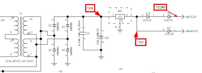
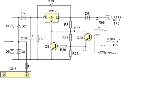
    Na płytce 640-0395B-Z_REV02
    APC Back-UPS Pro 550 BR550GI - Brak ładowania akumulatora

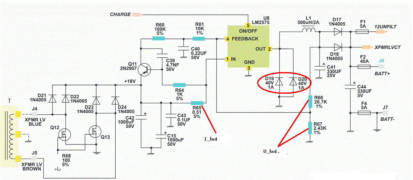
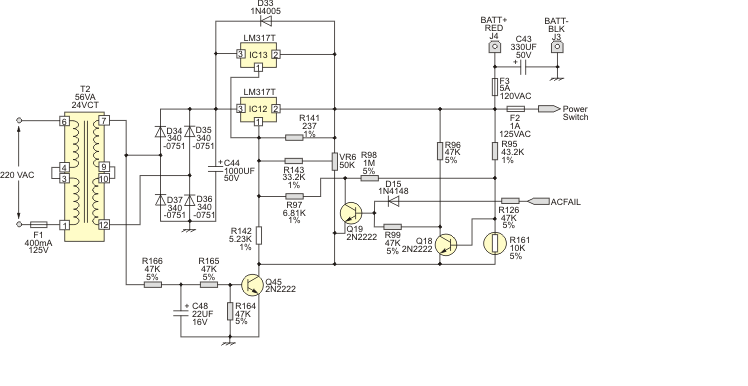
    PowerCom KIN 425/625AP ( z ogranicz. pradowym)

    APC Back-UPS Pro 550 BR550GI - Brak ładowania akumulatora
    Rys.1 i rys.2
    APC Back-UPS Pro 550 BR550GI - Brak ładowania akumulatora APC Back-UPS Pro 550 BR550GI - Brak ładowania akumulatora

    Uwyj. (Uład.) ustala R7/R38. Czujnik prądowy (ustala prąd ogranicz,) R51

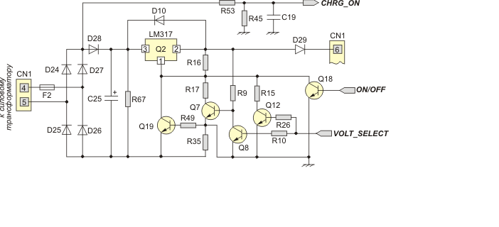
    Ponizej opis dotyczy rys.1
    Spoiler:
    VOLT_SELECT, which is a discrete signal and is generated by a microprocessor. This signal changes the parameters of the resistive divider that sets the output voltage of the stabilizer, and in particular the resistance of the "lower" resistor (R2 in Fig.4). Setting the VOLT_SELECT signal to a high level opens the transistor Q12 and locks the Q7. As a result, the" lower " resistor of the divider becomes the resistor R15. Setting the VOLT_SELECT signal to a low level leads to the opening of the transistor Q7 and closing Q12, resulting in a "lower" resistor divider becomes R17 C other resistance rating, which ultimately leads to a change in the output voltage of the charger.

    Switching on and off the charger is carried out by the signal on / OFF and transistor Q18, when you open the control terminal of the stabilizer LM317 (cont.1) shunted to the "ground". Current limitation, as usual, is carried out by the transistor Q19, which, in turn, is controlled by the current sensor – resistor R35.

    In the diagram shown in Fig.11 you can also see the presence of a charger sensor consisting of R53, R45 and C19. This sensor generates a CHRG_ON signal as soon as the supply voltage of the primary network appears at the UPS input. This signal with its high level informs the microprocessor about the presence of the mains voltage and the possibility of starting the battery charging process. It is on this signal that the microprocessor sets the on/OFF signal to a low level, which leads to the start of the charger. In principle, this sensor could be called a network voltage sensor.
  • REKLAMA
  • #5 17639186
    sunlux
    Poziom 20  
    Posty: 653
    Pomógł: 20
    Ocena: 120
    lisek napisał:
    Na razie z pomiarów wynika, że uszkodzone są:
    - bezpiecznik F2 1A 250V
    - przetwornica IC2 TNY278PN (ma wypaloną dziurę)
    - oba kondensatory 22µF/400V na płytce TL4

    Zapewne stary akumulator dawał zwarcie. Dziwi mnie tylko fakt, że oba kondensatory 22µF/400V są uszkodzone. Jutro powinny już być części to wymienię i napisze czy pomogło.
  • #6 17682607
    sunlux
    Poziom 20  
    Posty: 653
    Pomógł: 20
    Ocena: 120
    Witam ponownie.

    Po wymianie tych 4 szt. elementów zasilacz prawidłowo ładuje akumulator. Dziwi mnie tylko sytuacja, że kiedy ładuje akumulator EUROPOWER 12V 7Ah napięcie rośnie do 14,2VDC (czyli trochę zbyt dużo), a kiedy już ten akumulator naładuje się napięcie wynosi 13,7-13,8VDC (czyli prawidłowo).
  • #7 19390352
    pavgoust
    Poziom 1  
    Posty: 1
    Ocena: 2
    Drodzy zebrani,

    Mam UPS z płytą pokazane poniżej jako omówione w tym wątku APC Back-UPS Pro 550 BR550GI do 640-1172A-Z_REV05. Ten sam problem, brak ładowania. Zastąpiłem następujące: IC2 - TNY278PN, 22 µF/400V na podniesionej płycie i nadal nie działa. Czy jest coś innego, co jest związane z obwodem ładowania, który się psuje?

    Dziękuję Ci
    PS.
    Przepraszam, ale moim językiem ojczystym nie jest polski, tłumaczenie Google tutaj.

Podsumowanie tematu

✨ Użytkownik zgłasza problem z zasilaczem APC Back-UPS Pro 550 BR550GI, który nie ładuje akumulatora po jego rozładowaniu. Po wymianie uszkodzonych elementów, takich jak bezpiecznik F2, przetwornica IC2 TNY278PN oraz kondensatory 22μF/400V, zasilacz zaczął prawidłowo ładować akumulator. Zauważono jednak, że napięcie ładowania wzrasta do 14,2VDC, co jest nieco za wysokie, ale po naładowaniu akumulatora stabilizuje się na 13,7-13,8VDC. Inny użytkownik z podobnym problemem wymienił te same komponenty, ale nadal nie uzyskał poprawy, co sugeruje, że mogą istnieć inne uszkodzone elementy w obwodzie ładowania.
Wygenerowane przez model językowy.
REKLAMA