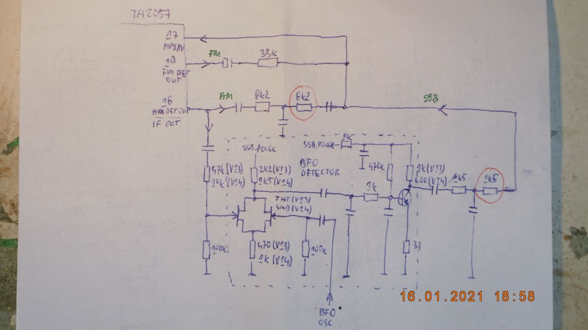
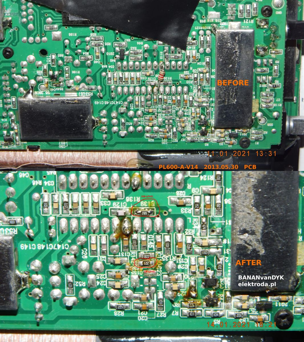
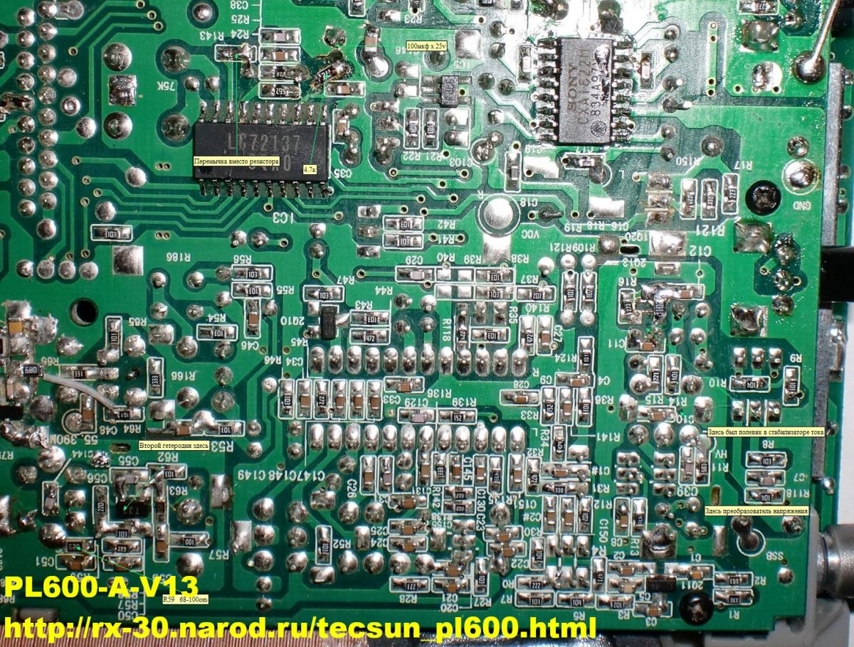
Odbiornik Tecsun PL-600 z podłączoną anteną zewnętrzną, po uderzeniu pioruna w działkę sąsiada zamilkł na zakresie fal krótkich. Zgodnie z sugestią na stronie https://swling.com/blog/2013/12/repairing-the...sun-pl-600-after-electrostatic-discharge-esd/ , uznałem że tranzystor FET 2SK2394 uległ uszkodzeniu. W związku z brakiem dostępności próbowałem z BF545, lecz okazało się że nie działa (sądziłem że problem tkwi w różnicy napięcia progowego Ugs). Kiedy udało mi się zdobyć 2SK2394, po wlutowaniu okazało się że radio nadal nic nie odbiera... Zacząłem drążyć temat i okazało się że schemat dostępny w internecie (reverse engineering z chińskiej gazety) jest błędny. Przerysowałem na nowo schemat, lecz nie mogłem znaleźć przyczyny problemu.
Schemat od PL-660 oraz schemat reverse-engineering od PL-880 (z radioscaner.ru) pomógł mi zrozumieć zasadę działania radioodbiornika. Diody D1 i D11 służą do przełączania pomiędzy zakresem SW a MW/LW, dioda D2 służy jako ogranicznik w przełączniku DX/LOC w wyniku zmiany napięcia na wejściu AM-MIX1. Jak widać Tecsun PL-600 używa wyłącznie anteny ferrytowej na zakresach MW/LW, co jest przyczyną słabej czułości na tych zakresach. Schemat układu przełącznika FM DX/NORM/LOC wyjaśnia dlaczego na pozycji NORM odbiornik wydaje się najmniej czuły.
Przyczyną okazała się przebita dioda D1, która wykazywała napięcie Uf 0.3V w kierunku przewodzenia i Uf 0.7V w kierunku zaporowym. Schemat PL-600 i PL-660 sugeruje diodę 1N135 (nie produkowana), a schemat PL-880 sugeruje diodę 1SS135 (praktycznie niedostępna w sprzedaży). Jest to z pewnością dioda przełączająca PIN (band switch diode). Internet sugeruje użycie zamiennika 1SS133 dla 1SS135. Inne zamienniki (przeznaczone jako band switch diode) to: 1SS110, 1SS265. Oryginalna dioda wykazuje Uf 0.75V, natomiast zwykła dioda 1N4148 wykazuje Uf 0.5V. Udało mi się znaleźć jakąś diodę z Uf 0.7V, wlutowałem ją od drugiej strony aby było łatwiej wymienić.
Analiza schematu sugeruje że radioodbiornik może posiadać wbudowany bias do anteny aktywnej AM (3.5V), lecz układ odbiornika nie przepuszcza sygnałów MW/LW...
------------
Tecsun PL-600 repair after a lightning storm
The Tecsun PL-600 receiver with an external antenna connected, after a lightning strike in the neighbor's field, fell silent on the short wave band. As suggested on https://swling.com/blog/2013/12/repairing-the...sun-pl-600-after-electrostatic-discharge-esd/, I think the 2SK2394 FET transistor is damaged. Due to the lack of availability, I tried with the BF545, but it turned out that it does not work (I thought the problem was the difference in the threshold voltage Ugs). When I managed to get 2SK2394, after soldering, the radio still does not receive anything... I started to drill down on the topic and it turned out that the schematic available on the internet (reverse engineering from a Chinese newspaper) was wrong. I redrawed the schematic but couldn't find the cause of the problem.
The schematic diagram from PL-660 and the reverse-engineering diagram from PL-880 (from radioscaner.ru) helped me understand how the radio works. The D1 and D11 diodes are used to switch between the SW and MW / LW ranges, the D2 diode serves as a limiter in the DX / LOC switch due to the voltage change at the AM-MIX1 input. As you can see, Tecsun PL-600 uses only a ferrite antenna in MW / LW bands, which is the reason for poor sensitivity in these bands. The schematic diagram of the FM DX / NORM / LOC switch explains why the receiver appears to be the least sensitive in the NORM position.
The reason was the shorted diode D1, which showed a voltage of Uf 0.3V in the forward direction and Uf 0.7V in the reverse direction. The diagram of the PL-600 and PL-660 suggests a 1N135 diode (not produced), and the diagram of the PL-880 suggests a 1SS135 diode (practically not available for sale). It is definitely a PIN switch diode. The internet suggests using a 1SS133 replacement for 1SS135. Other replacements (intended as band switch diode) are: 1SS110, 1SS265. The original diode shows Uf 0.75V, while the regular 1N4148 diode shows Uf 0.5V. I managed to find a diode with Uf 0.7V, I soldered it from the other side to make it easier to replace.
The analysis of the diagram suggests that the radio may have a built-in bias to the active AM antenna (3.5V), but the receiver circuit does not pass MW / LW signals...
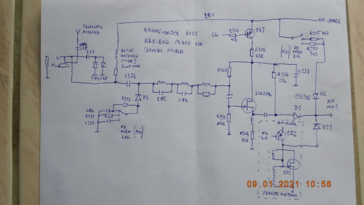
Schemat od PL-660 oraz schemat reverse-engineering od PL-880 (z radioscaner.ru) pomógł mi zrozumieć zasadę działania radioodbiornika. Diody D1 i D11 służą do przełączania pomiędzy zakresem SW a MW/LW, dioda D2 służy jako ogranicznik w przełączniku DX/LOC w wyniku zmiany napięcia na wejściu AM-MIX1. Jak widać Tecsun PL-600 używa wyłącznie anteny ferrytowej na zakresach MW/LW, co jest przyczyną słabej czułości na tych zakresach. Schemat układu przełącznika FM DX/NORM/LOC wyjaśnia dlaczego na pozycji NORM odbiornik wydaje się najmniej czuły.
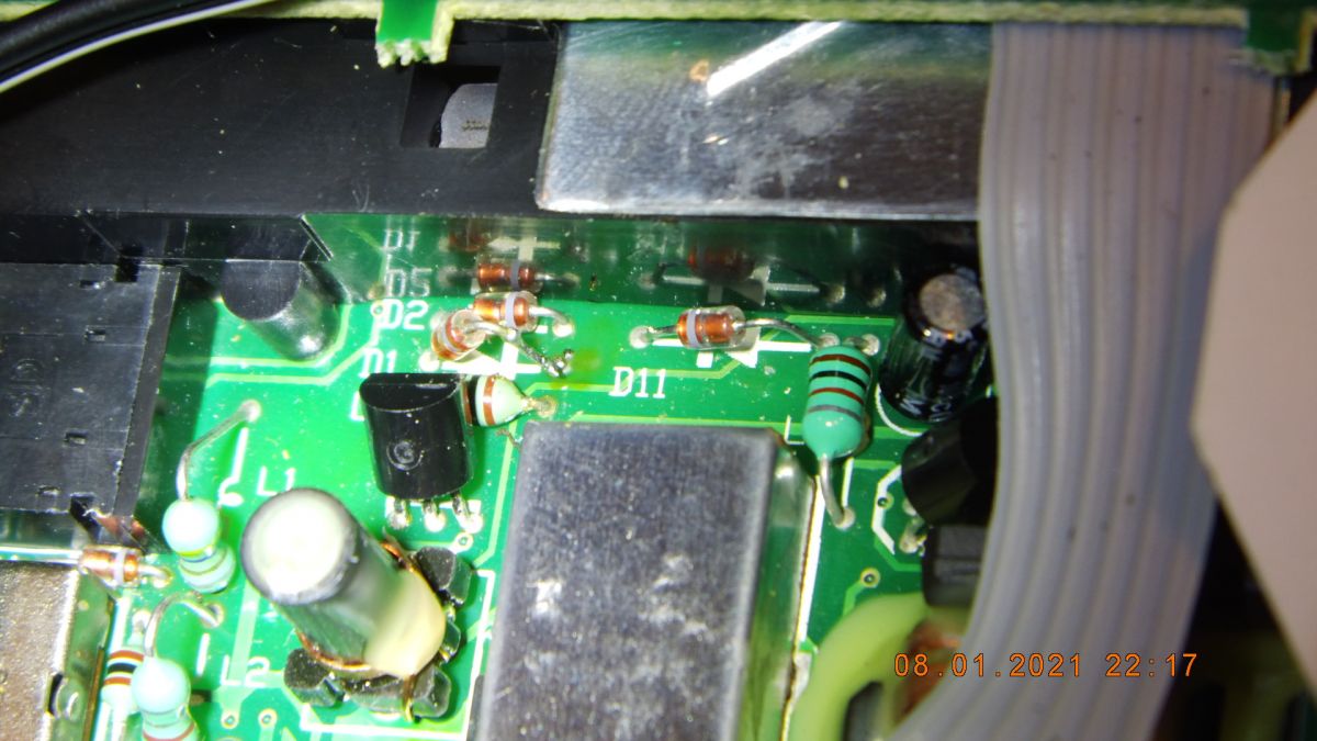
Przyczyną okazała się przebita dioda D1, która wykazywała napięcie Uf 0.3V w kierunku przewodzenia i Uf 0.7V w kierunku zaporowym. Schemat PL-600 i PL-660 sugeruje diodę 1N135 (nie produkowana), a schemat PL-880 sugeruje diodę 1SS135 (praktycznie niedostępna w sprzedaży). Jest to z pewnością dioda przełączająca PIN (band switch diode). Internet sugeruje użycie zamiennika 1SS133 dla 1SS135. Inne zamienniki (przeznaczone jako band switch diode) to: 1SS110, 1SS265. Oryginalna dioda wykazuje Uf 0.75V, natomiast zwykła dioda 1N4148 wykazuje Uf 0.5V. Udało mi się znaleźć jakąś diodę z Uf 0.7V, wlutowałem ją od drugiej strony aby było łatwiej wymienić.
Analiza schematu sugeruje że radioodbiornik może posiadać wbudowany bias do anteny aktywnej AM (3.5V), lecz układ odbiornika nie przepuszcza sygnałów MW/LW...
------------
Tecsun PL-600 repair after a lightning storm
The Tecsun PL-600 receiver with an external antenna connected, after a lightning strike in the neighbor's field, fell silent on the short wave band. As suggested on https://swling.com/blog/2013/12/repairing-the...sun-pl-600-after-electrostatic-discharge-esd/, I think the 2SK2394 FET transistor is damaged. Due to the lack of availability, I tried with the BF545, but it turned out that it does not work (I thought the problem was the difference in the threshold voltage Ugs). When I managed to get 2SK2394, after soldering, the radio still does not receive anything... I started to drill down on the topic and it turned out that the schematic available on the internet (reverse engineering from a Chinese newspaper) was wrong. I redrawed the schematic but couldn't find the cause of the problem.
The schematic diagram from PL-660 and the reverse-engineering diagram from PL-880 (from radioscaner.ru) helped me understand how the radio works. The D1 and D11 diodes are used to switch between the SW and MW / LW ranges, the D2 diode serves as a limiter in the DX / LOC switch due to the voltage change at the AM-MIX1 input. As you can see, Tecsun PL-600 uses only a ferrite antenna in MW / LW bands, which is the reason for poor sensitivity in these bands. The schematic diagram of the FM DX / NORM / LOC switch explains why the receiver appears to be the least sensitive in the NORM position.
The reason was the shorted diode D1, which showed a voltage of Uf 0.3V in the forward direction and Uf 0.7V in the reverse direction. The diagram of the PL-600 and PL-660 suggests a 1N135 diode (not produced), and the diagram of the PL-880 suggests a 1SS135 diode (practically not available for sale). It is definitely a PIN switch diode. The internet suggests using a 1SS133 replacement for 1SS135. Other replacements (intended as band switch diode) are: 1SS110, 1SS265. The original diode shows Uf 0.75V, while the regular 1N4148 diode shows Uf 0.5V. I managed to find a diode with Uf 0.7V, I soldered it from the other side to make it easier to replace.
The analysis of the diagram suggests that the radio may have a built-in bias to the active AM antenna (3.5V), but the receiver circuit does not pass MW / LW signals...