






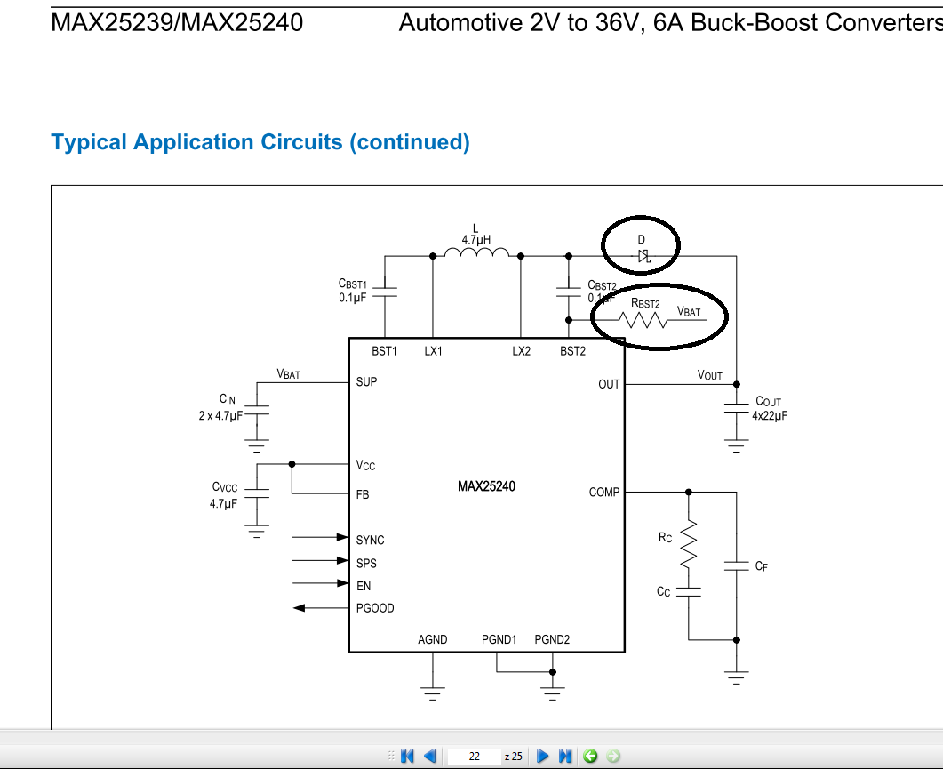
Zanzaczyłem je na obrazku. W schemacie devboard'a mają te elementy, ale nie było wytłumaczenia. Sam pdf ze strony producenta o tych elementach nie wspomina. Trafiłem pdfa na stronie mousera i tam już coś na ten temat się znalazło.
https://www.mouser.pl/ProductDetail/Analog-De...240AFFF-VY%2b?qs=MyNHzdoqoQJSGLHXjll09Q%3D%3D
Cytat:High-Power Application
The MAX25239/MAX25240 have two input current-limit options: 8.2A and 10A. For a 10A input current-limit application,
a Schottky diode between LX2 and converter output and a 10kΩ resistor between SUP and BST2 are recommended.
See the Figure 4 typical application circuit and the Applications Information section for Schottky diode selection.
Cytat:Schottky Diode Selection
For a 10A ILIM application, a Schottky diode between LX2 and the converter output is recommended when using
the MAX25240. Based on the output voltage, the Schottky diode should have maximum reverse voltage to sustain a
maximum LX2 voltage. It is also required to have a 5A (min) forward current and less than a 0.5V forward voltage.
W czym ta dioda i rezystor pomaga, i dlaczego powinna mieć 5A min?. Zasilanie planuję od 6V, na wyjściu potrzebuje 15V 5A, czyli jest szansa że osiągnie te 10A na wejściu i lepiej to dać
