logo elektroda
logo elektroda
X
logo elektroda
REKLAMA
REKLAMA
Adblock/uBlockOrigin/AdGuard mogą powodować znikanie niektórych postów z powodu nowej reguły.

LED naświetlarka do PCB

reddwarf 17 Maj 2011 17:41 17481 20
REKLAMA
  • LED naświetlarka do PCB

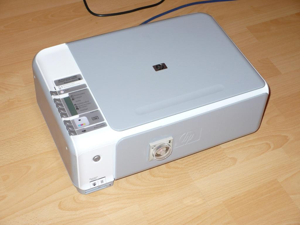
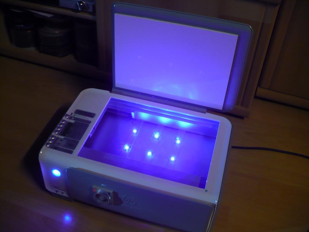
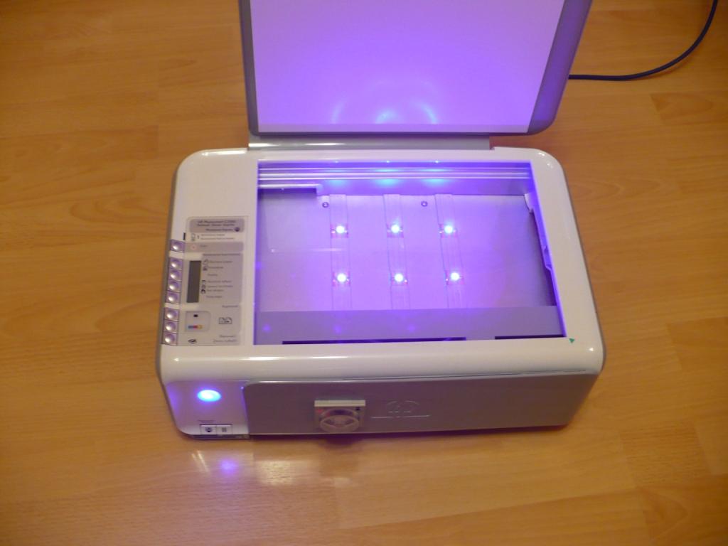
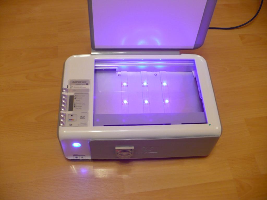
    LED naświetlarka do PCB.
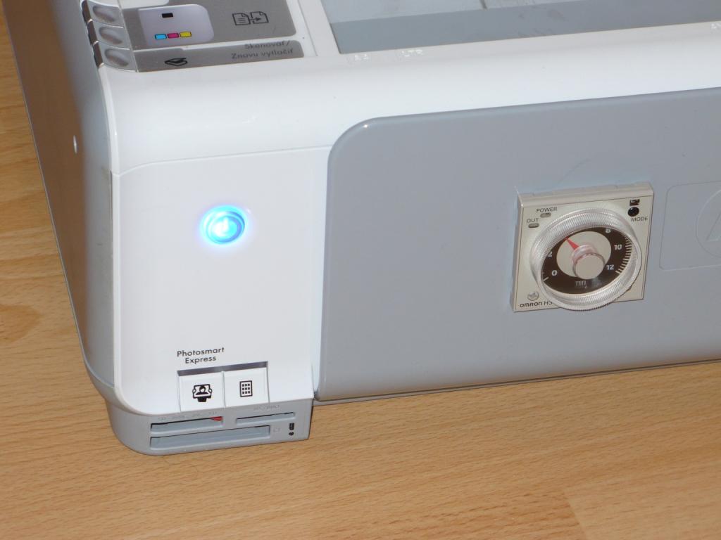
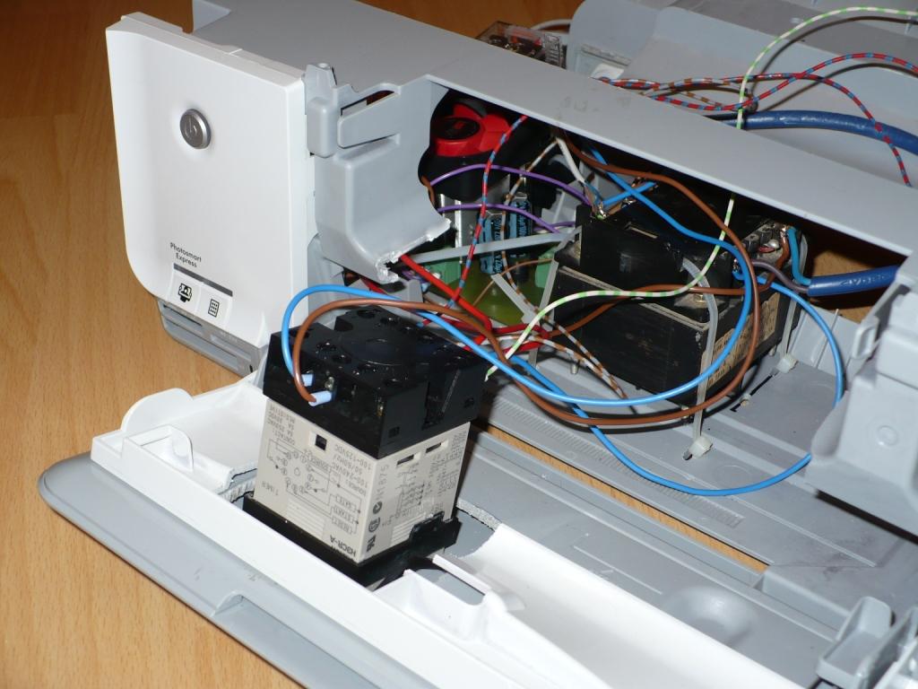
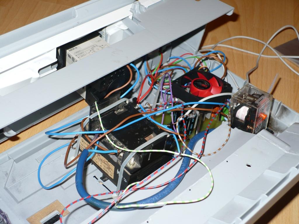
    Kryt zo starej tlaciarne HP Photosmart C3180
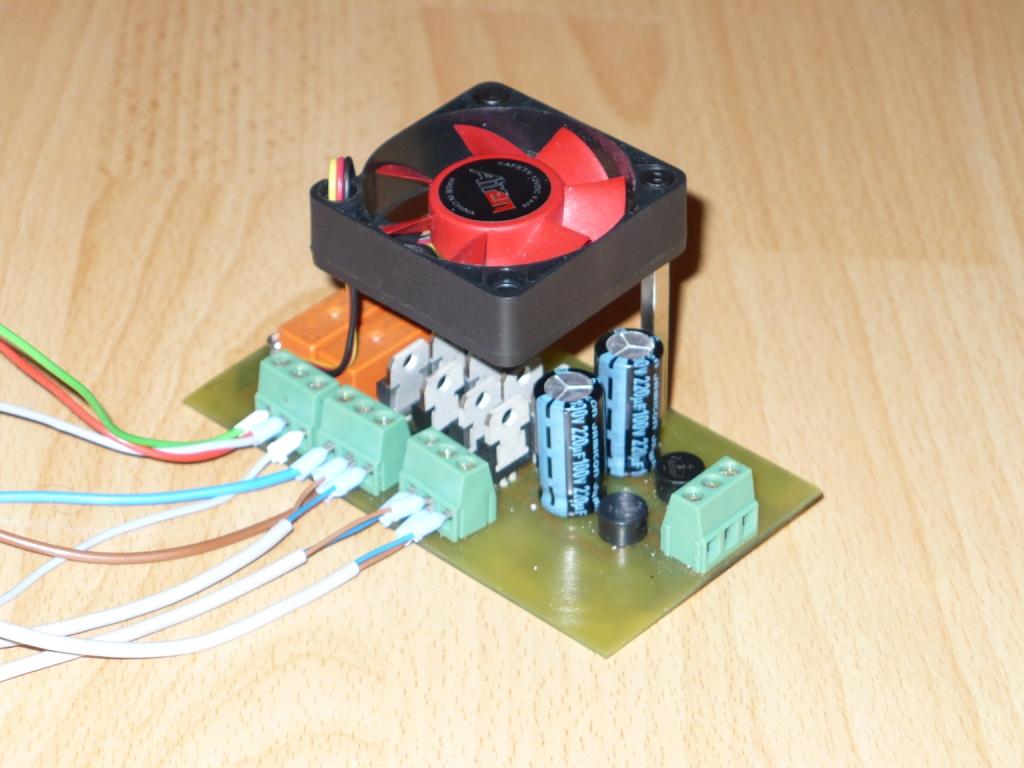
    Transformator zo stareho TV
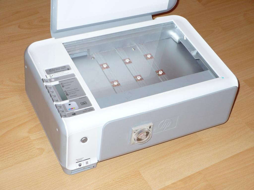
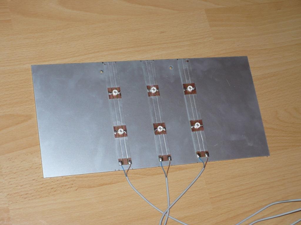
    LED: 6x1W UV
    Casovac: Omron H3CR-A

    Czas potrzebny do oświetlenia 5~6 minut.

    Przepraszam za błąd i krótki opis. Pismo przez Google Translator.
    Ja jestem ze Słowacji.


    . . . . . . . . . . . . . . . . . . . . . . . . . . . . . . . . . . . . . . . .

    LED naświetlarka do PCB LED naświetlarka do PCB LED naświetlarka do PCB

    LED naświetlarka do PCB LED naświetlarka do PCB LED naświetlarka do PCB

    LED naświetlarka do PCBLED naświetlarka do PCBLED naświetlarka do PCB

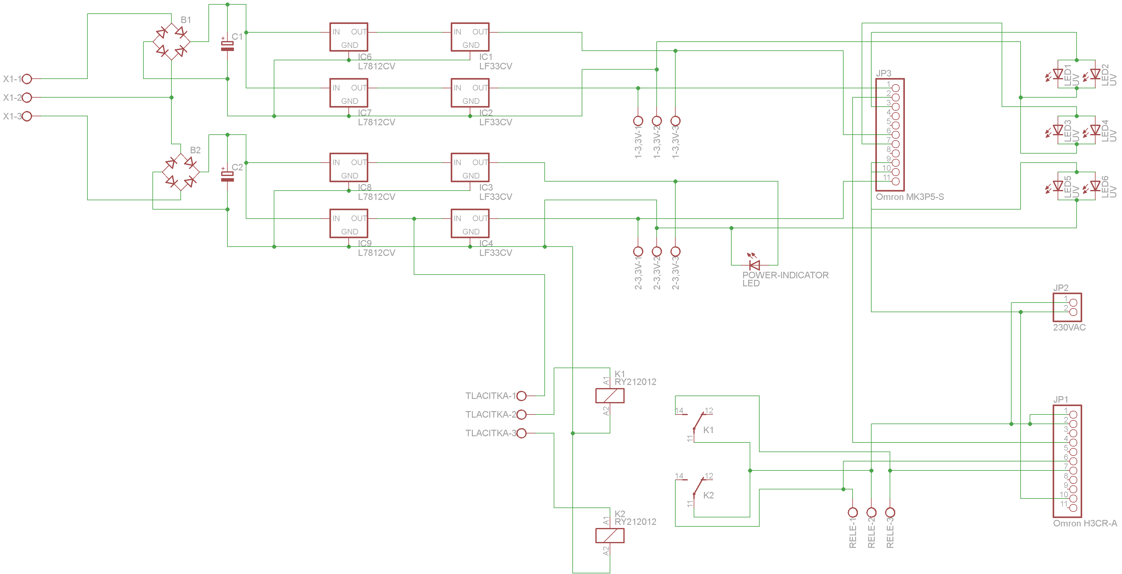
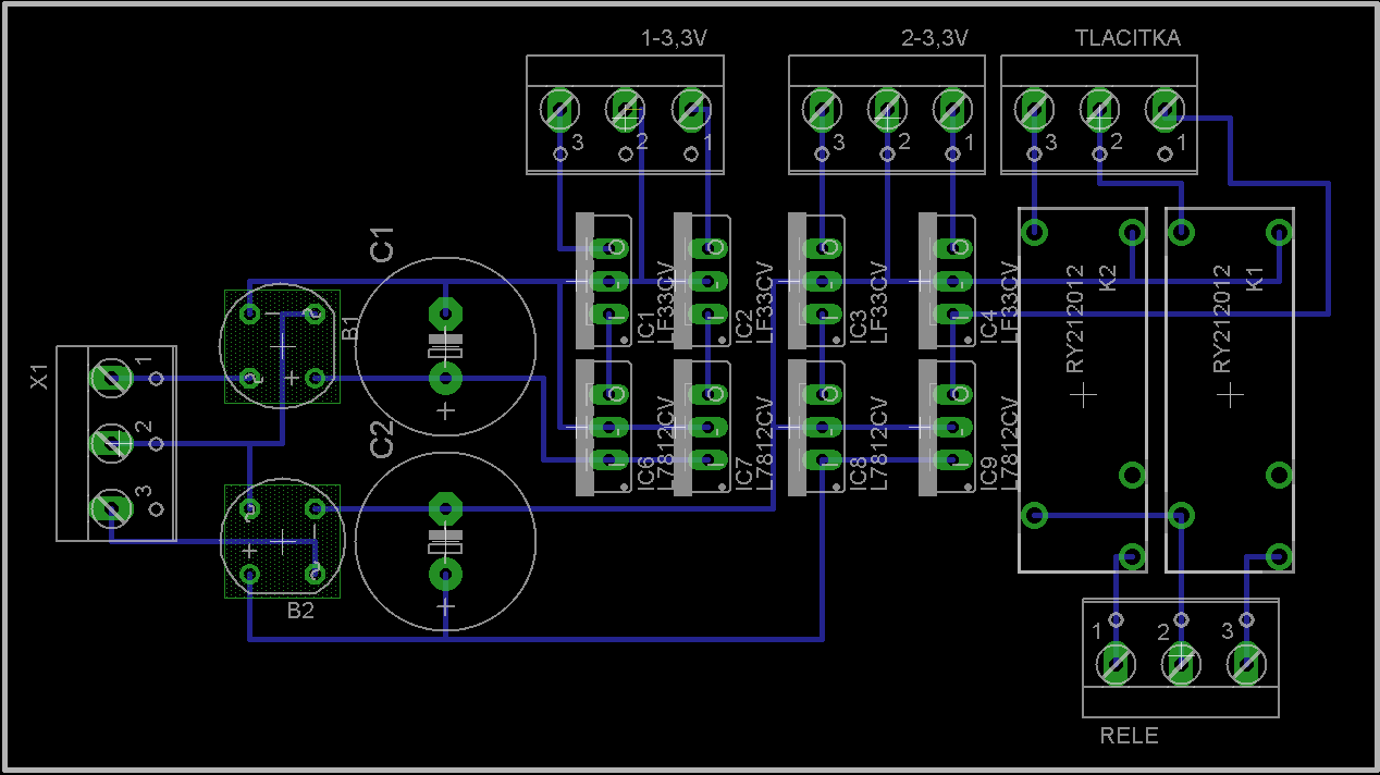
    Wstawiłem zdjęcie na początek wiadomości zgodnie z zasadami działu DIY Konstrukcje. Pomimo, że kolega jest nowy i nie zna jeszcze zasad działu, temat zostawiam. Jak jest możliwość to proszę wstawić schemat. Dziękuję.

    I put a picture at the beginning of the post according to the DIY Constructions rules. Although the friend is new and does not know the rules about section DIY I decided to leave the topic here. If it is possible please insert the schematics. Thank you.

    /Faces/

    Fajne? Ranking DIY
    O autorze
    reddwarf
    Poziom 10  
    Offline 
    reddwarf napisał 5 postów o ocenie 79. Mieszka w mieście Slovakia. Jest z nami od 2010 roku.
  • REKLAMA
  • #2 9516914
    kacper1664
    Poziom 12  
    Posty: 35
    Ocena: 2
    Write a description in English and try include more details about your construction.
    How it works? It`s going to be a nice topic here :)

    Do modera - wybacz za angielski, nawet jeśli pokaleczony, ale tak się możemy szybciej dogadać.
  • #3 9516919
    Miguel573
    Poziom 11  
    Posty: 43
    Ocena: 48
    Hi. Very nice project. I want to see the schematics. How much it cost ? What is type of diodes use in your project ?

    Best regards
  • #4 9516994
    c4r0
    Poziom 36  
    Posty: 4346
    Pomógł: 155
    Ocena: 565
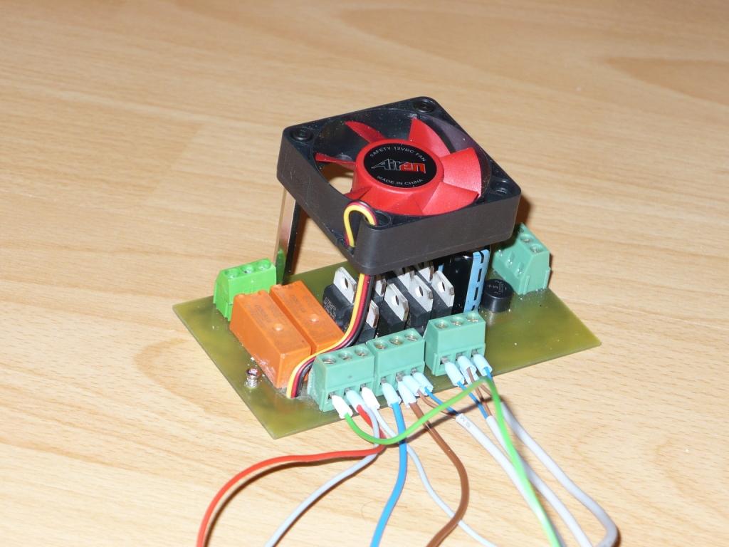
    Please include the schematic of this project. Why did you put a fan on those TO-220 components (LDOs?) instead of a heatsink?

    I'd suggest not only to write in English (regardless how good your English is) but also in Slovakian. Sometimes it's easier for a Polish guy to understand Slovakian writing than a version automatically translated into Polish :) When you write your posts in Slovakian you are sure that the description actually makes sense (automatic translation very often doesn't) and users who want an automatically translated version can copy-and-paste it to google translate by themselves.
  • REKLAMA
  • #5 9517056
    MichałKob
    Poziom 20  
    Posty: 376
    Pomógł: 26
    Ocena: 59
    Definitely a nice idea! One thing tricks me though, is the LED light intensity even enough? There are only 6 LEDs and I think the PCB could get uneven exposure. That would be a real drawback, especially keeping the UV LEDs cost in mind. Does the LED spectrum match the photoresist requirements?
  • #6 9517285
    farrix
    Poziom 17  
    Posty: 260
    Pomógł: 7
    Ocena: 12
    Może kolega napisać jak wygląda naświetlanie diodami w stosunku do świetlówki, co szybciej wykona swoją pracę?
  • #7 9517311
    Miguel573
    Poziom 11  
    Posty: 43
    Ocena: 48
    Przetłumaczę Cię farrix mam nadzieję że dobrze:
    Farrix translate:
    Friend, can you tell me what is the difference between diodes and fluorescent lamp, which is faster in work ?
  • #8 9517944
    REVISOR
    Poziom 25  
    Posty: 701
    Pomógł: 58
    Ocena: 56
    Witam też zrobiłem sobie naświetlarkę z ledów tylko dałem o wiele gęściej ledów i oczywiście dałem ledy z szerokim kątem świecenia 120stopni fakt faktem były o wiele mniejszej mocy niż te z tego tematu, miały one płaskie czoło, jak są rozstawione rzadziej to płytka nierównomiernie się naświetla, można to zminimalizować używając jakiejś warstwy rozpraszającej lub oddalając ledy od naświetlanej płytki, czas naświetlania podobny ok 5minut, zalety to chyba niski pobór prądu i zależnie od sposobu wykonania taka naświetlarka może mieć małe gabaryt, jako maskę stosowałem specjalna matowa folie która świetnie chłonęła toner z drukarki laserowej. używałem popularnego positiva ale płytki kupione z fabryczną fotoczułą maską i prawie wcale nie chciały się trawić być może tamten lakier był czuły na inny zakres fal niż te emitowane przez moje ledy.
  • REKLAMA
  • #9 9518240
    reddwarf
    Poziom 10  
    Posty: 5
    Ocena: 79
    My English is also not good. For voltage regulators, I had to put coolers. Just thicker aluminum. Source is very simple. Voltage is over 12V L7812CV and subsequently through LF33CV to 3.3 V.

    UV LED: 22,83€ from ebay.com
    Omron H3CR-A (timer): 60€
    Omron MK3P5-S (3-contact relay): 14€
    LF33CV: 3,92€
    L7812CV: 0,80€
    +connectors, etc.

    Total price is about 100€, but if you replace timer with your own timer, price can be significantly lower.

    I dont have experience with lamps and therefore I can not compare. Time for one board is about 5-6 minutes. Angle of LED is great (140°), the lighting should be evenly. Schematic and board is in attachment

    LED is from ebay: Link

    Angle: 140°
    Intensity Luminous (Iv): 10 LM
    DC Forward Voltage (VF): 3.0 ~ 3.6 Vdc
    Emitted Color : UV (400nm)

    SK:
    Moja angličtina nie je dobra. Na stabilizátory som musel dať chladiče. Stačí hrubší hliník. Zdroj je veľmi jednoduchy. Napätie je stabilizované cez L7812CV na 12V a potom cez LF33CV na 3,3V

    Celková cena je okolo 100€ ale ak použijete vlastný časovač, cena bude oveľa nižšia.

    Nemám skúsenosti s žiarivkami, preto neviem porovnať. Čas potrebný na osvetlenie je okolo 5-6 minút. Uhol LED je veľký (140°), a teda doska by mala byť osvetlená rovnomerne. Schéma a doska je v prílohe.

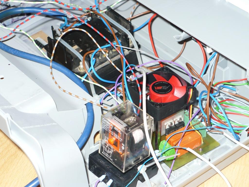
    My first test board:
    LED naświetlarka do PCB

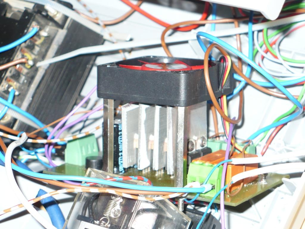
    Added simple heatsink:
    LED naświetlarka do PCB

    LED naświetlarka do PCBLED naświetlarka do PCBLED naświetlarka do PCB

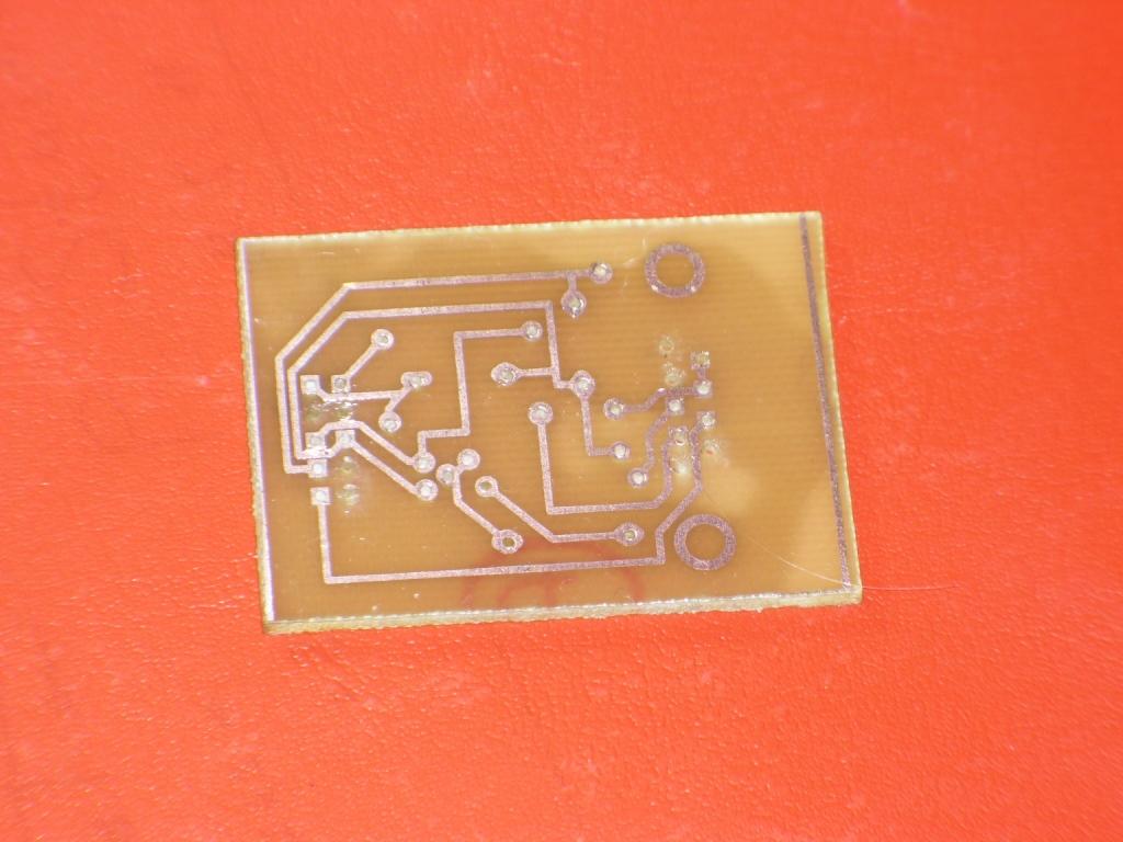
    UV LED board:
    LED naświetlarka do PCB
    Załączniki:
    • UV.zip (130.29 KB) Musisz być zalogowany, aby pobrać ten załącznik.
  • #10 9518307
    c4r0
    Poziom 36  
    Posty: 4346
    Pomógł: 155
    Ocena: 565
    reddwarf napisał:
    For voltage regulators, I had to put coolers. Just thicker aluminum.
    OK, in the new pictures I see that you actually have a fan AND some kind of heat sinks. That makes more sense.

    reddwarf napisał:
    I dont have experience with lamps and therefore I can not compare.
    Do you have any idea what would be the cost of building it with fluorescent UV lamps? Wouldn't it be cheaper to achieve the same results with lamps instead of that fancy LEDs?

    reddwarf napisał:
    Angle of LED is great (140°), the lighting should be evenly.
    Angle 140° you say, but how is it defined? I'm pretty sure that light intensity among this angle is not even. Check the datasheet (if you have the LED's part number) and you should find there an angular intensity characteristic. I would expect the light to be significantly uneven in your design, however, it's probably possible to find a "sweet spot" for exposure time to make it work for most PCBs. But I would consider adding there some kind of diffuser anyway... assuming it's easy to find appropriate material for diffusing UV in that range. Or more LEDs of course, but that will drive up the cost.

    The last picture: do you have the LEDs in that pairs connected in parallel? In the picture it looks like you do, and it's not a good idea to do it this way.

    Your English is good enough to understand what you mean, so don't worry about it and post in English :)
  • #11 9518331
    reddwarf
    Poziom 10  
    Posty: 5
    Ocena: 79
    c4r0 napisał:
    Do you have any idea what would be the cost of building it with fluorescent UV lamps? Wouldn't it be cheaper to achieve the same results with lamps instead of that fancy LEDs?


    Price per lamp is similar. The lamps are needed inductors etc. Originally I planned to sodium vapor lamp but I discourage formation of ozone. I have an inkjet printer. Master prints on tracing paper, not film. Paper slightly diffuses light.

    c4r0 napisał:
    Angle 140° you say, but how is it defined? I'm pretty sure that light intensity among this angle is not even. Check the datasheet (if you have the LED's part number) and you should find there an angular intensity characteristic. I would expect the light to be significantly uneven in your design, however, it's probably possible to find a "sweet spot" for exposure time to make it work for most PCBs. But I would consider adding there some kind of diffuser anyway... assuming it's easy to find appropriate material for diffusing UV in that range. Or more LEDs of course, but that will drive up the cost.


    On ebay are often misleading information. Angle may be smaller than indicated, but it seems to me a sufficient and relatively large. Datasheet I can not find, since I do not know or who is the manufacturer. Manufacturer is not listed in description on ebay.

    Yes, I have LED pairs connected in parallel. Why is it not good? I think it's better than serial. Each stabilizer are strong enough to be able to power the 2 LEDs.
  • #12 9518539
    c4r0
    Poziom 36  
    Posty: 4346
    Pomógł: 155
    Ocena: 565
    I would not buy an "unknown" LED like that from eBay (no manufacturer and part number info = unknown) unless the price is low enough in compare to "known" LEDs that it makes it worth to take the risk. I assume that's what happened in your case. Anyway, if there's no technical specification available for those LEDs you can't do more that just try and see what happens. But I think I don't really have to mention that :)

    Parallel connection is bad because voltage drop of LEDs is always slightly different from part to part. It means that supplied current will never be divided perfectly even between LEDs connected in parallel, and you don't have any control of what that current distribution will happen to be. Technically, when you connect any components like that in parallel, you should add small resistors in series with each component to help distribute current evenly. In case of LEDs connection in series is almost always better and more electrically efficient and the only problem might be higher voltage needed to power LEDs connected in series. In your case, you have 12V on board there so powering two UV LEDs in series should not be a problem I guess (I don't know what's the voltage drop though, but this is easy to measure). My rule of thumb is NEVER connect LEDs in parallel and probably majority of guys here will agree.
  • #13 9518709
    c64club
    Poziom 18  
    Posty: 342
    Pomógł: 13
    Ocena: 70
    Wouldn't it be nice to take some "matte" layer between LEDs and PCB? It could give more "antialiased" lighting instead of "six lighter points and their darker ambient".
  • #14 9519501
    profesorek_96
    Poziom 16  
    Posty: 238
    Ocena: 11
    This imagesetter very nice. J think the imagesetter is timering.
    Sorry for my english.
  • REKLAMA
  • #15 9520200
    c4r0
    Poziom 36  
    Posty: 4346
    Pomógł: 155
    Ocena: 565
    BoBeR/Apidya napisał:
    Wouldn't it be nice to take some "matte" layer between LEDs and PCB? It could give more "antialiased" lighting instead of "six lighter points and their darker ambient".
    I think it would, but if you do that there will always be some light loss. The question is, can you easily find a material for such a diffuser that will work good enough in UV range (i.e. diffusing but not too lossy).
  • #17 9525777
    c4r0
    Poziom 36  
    Posty: 4346
    Pomógł: 155
    Ocena: 565
    To się robi na tzw. płytkach z fotorezystem. Poszukaj na allegro.
  • #18 9526403
    dariuszj
    Poziom 20  
    Posty: 441
    Pomógł: 33
    Ocena: 68
    Taką samą jakość lub lepszą osiągam na termotransferze. Jaki sens?
  • #19 9526452
    reddwarf
    Poziom 10  
    Posty: 5
    Ocena: 79
    dariuszj napisał:
    Taką samą jakość lub lepszą osiągam na termotransferze. Jaki sens?


    I think UV is better than iron.

    war40k napisał:
    Domyślam się że do naswietlania potrzebny jest schemat ścieżek wydrukowany na foli przezroczystej. A jaki płyn do malowania pcb jest potrzebny?


    The scheme should be printed on transparencies. I have an inkjet printer to print on tracing paper and the results are also good. I use this product: Link
  • #20 9527291
    c4r0
    Poziom 36  
    Posty: 4346
    Pomógł: 155
    Ocena: 565
    dariuszj napisał:
    Taką samą jakość lub lepszą osiągam na termotransferze. Jaki sens?
    To make a good PCB with this method you need at least "some" experience. Yo don't really need much experience to make a PCB with photoresist. Besides, I think that with photoresist you can get significantly narrower traces with lower clearances than with thermotransfer method. However, I've never used photoresist actually.
  • #21 9527541
    poorchava
    Poziom 18  
    Posty: 392
    Pomógł: 14
    Ocena: 23
    I used to experiment with UV led exposure. I've soldered 9 low cost (~0.2euro) 5mm diodes on a perfboard. Those were ordinary, low current (20 mA), 1500 mcd diodes. Effects were pretty good. With proper exposure timing the uneven lighting didn't afect the results.

    As for your design i'd some kind of current regulation and connect diodes in series (personally, i've used a LM317T in standard application for this). Just put some heatsink on LM317 and the resistor should be of an appropriate power rating for the current.

    As for the timer i'd use some kind of low cost AVR or PIC microcontroller. Paying that kind of money for simple timer doesn't make much sense to me.

    p.s.
    Despite my experiments with uv leds i still use a 0.5 kW halogen reflector for exposing pcbs. I'm capable of making 6 mil tracks quite reliably (of course, fuck-ups still happen, but more like during etching process)

Podsumowanie tematu

✨ Użytkownik zbudował naświetlarkę LED do PCB, wykorzystując diody UV 6x1W, transformator ze starego telewizora oraz timer Omron H3CR-A. Czas naświetlania wynosi 5-6 minut. W dyskusji poruszono kwestie dotyczące schematów, kosztów budowy, intensywności światła oraz porównania z lampami fluorescencyjnymi. Użytkownicy sugerowali dodanie dyfuzora dla równomierniejszego oświetlenia oraz omawiali różnice w efektywności między diodami LED a lampami fluorescencyjnymi. Wskazano również na problemy z nierównomiernym oświetleniem oraz konieczność stosowania odpowiednich stabilizatorów napięcia.
Wygenerowane przez model językowy.
REKLAMA